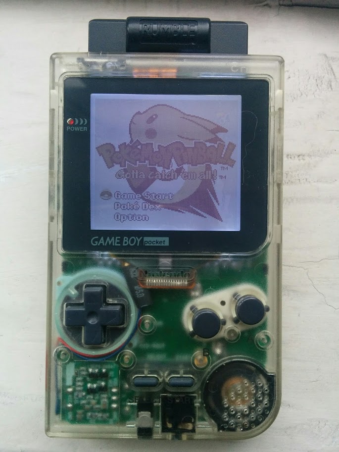
Some months ago I got the this LED panel from Hand-Held Legend to add backlight to the display of the Game Boy Pocket. The installation was quite simple and went without problems using the instructions provided and this useful video. As the panel is powered is connected to 5 V, a resistor of 100 or 150 \(\Omega\) is required to avoid a super bright backlight.

Game Boy Pocket with backlight.
Last weekend, I revisited my modded Game Boy and realized that I haven't used it as much as I expected.
The culprit?, the backlight itself, the intensity is good during daytime, but it's too bright to play at night in a dim room. To fix this, I decided to install a potentiometer and make it easily accessible to change the backlight intensity accordingly. This modification was a success and I am very satisfied with the result. Below I describe the procedure for modding the Game Boy Pocket.
Procedure
Materials
To install the LED backlight panel adjustable backlight, check the Required Equipment. For the wiring I used magnet wire 28 AWG, as it's easy to hide and pass through tight places. Also, sandpaper, a drill and drill bits are needed, this is be cause to add the potentiometer two extra modifications are needed:
-
Enlarging an existent hole in the PCB with a 3/64" or 1/16" drill bit.
-
Making a new hole in the plastic case with a 1/8" drill bit.
Beside the panel, a 100 \(\Omega\) resistor and 5 k\(\Omega\) potentiometer are needed. Due to the space limitations, I used as vertical skeleton trimmer potentiometer or trimpot.
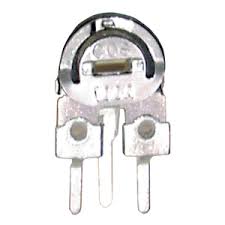
Skeleton vertical trimpot.
Installation
The electronic components: LED panel (D1). 100 \(\Omega\) resistor (R1) and the variable resistor (R2) are connected as follows.
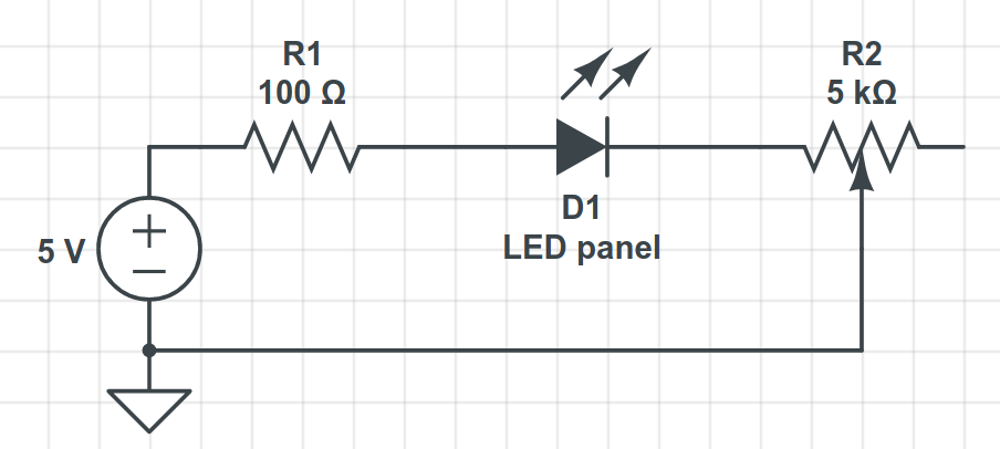
Electric circuit for adjustable backlight.
The fact that R1 and R2 are "before" and "after" the D1 does not matter, the y could be in any place in the series circuit. However, they were placed like that to facilitate the physical installation of the components. The installation can be broken in three parts:
- LED panel placement
- Connection to 5 V
- Trimpot placement and connection to ground
1. LED panel placement
For this first part, follow the instructions in this video:

2. Connection to 5 V
The positive connection of the LED panel is done through R1, and can be done to this point.
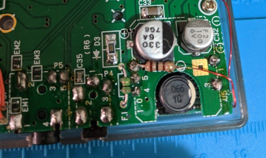
Connection to 5 V.
3. Trimpot placement and connection to ground
Let's prepare the trimpot. Remove the pins for the both the extreme connections. And by seen the trimpot from the back, place a drop of solder in the right connection.
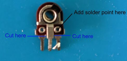
Preparing the trimpot.
Enlarge this existing through hole in the PCB with the 3/64" drill bit. This through hole connects two ground planes on each side of the PCB.
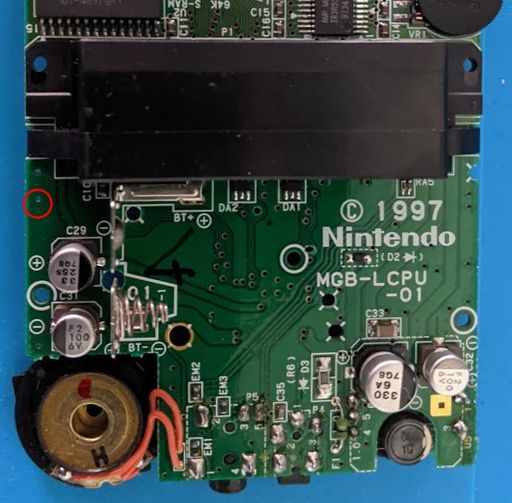
Through hole to enlarge.
With help of sandpaper and patience remove the paint around the new through hole on both sizes of the PCB and insert the trimpot facing back, with the position it will fit nicely in the case.
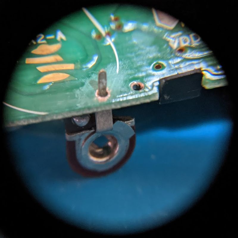
Placing trimpot.
Solder the negative connection of the LED panel to the trimpot terminal that has already solder.
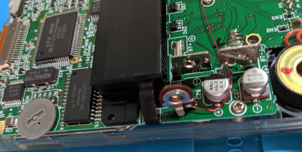
Connection to graound.
Finally, close the Game Boy Pocket and identify where the trimmer is make hole with the 1/16" drill bit in the case. In my case, I have a clear case, which makes the task way more easier.
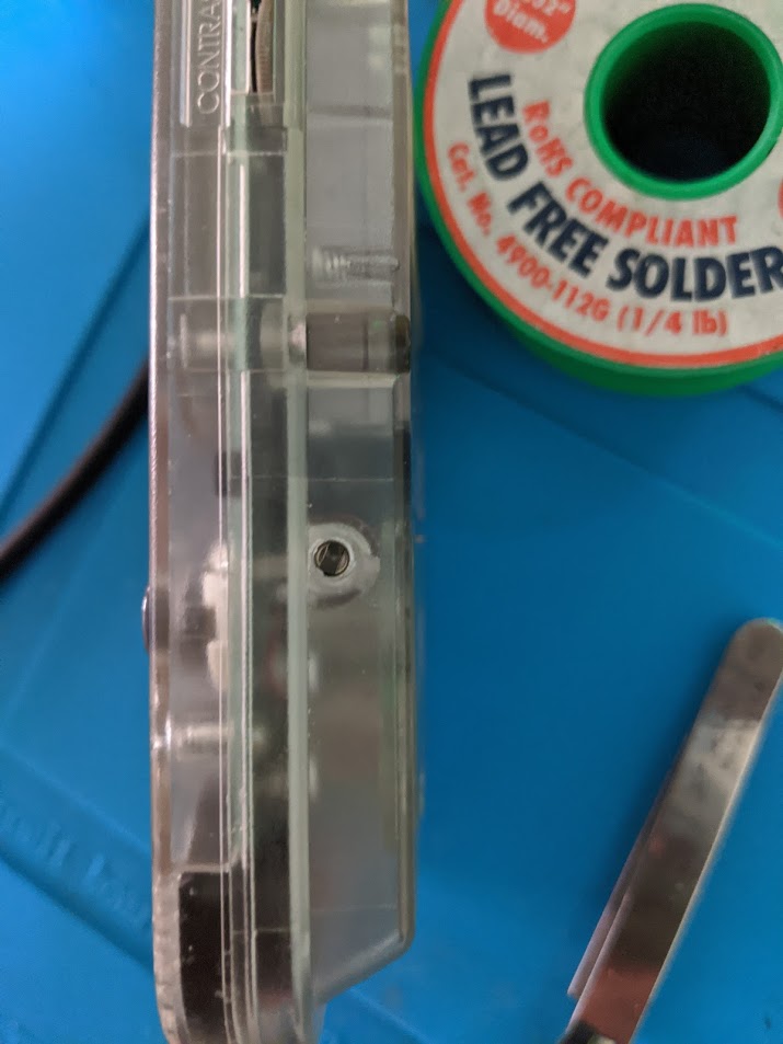
Game Boy Pocket case with hole
Close the Game Boy and enjoy the adjustable backlight.
Result
Game Boy Pocket with adjustable backlight.
For the moment, I need a small flat screwdriver to adjust the backlight intensity. I have in mind to 3D print a small piece to do adjustment, something like a watch crown.


Comments
comments powered by Disqus